This website is preserved for historical and scholarly reference and is no longer actively maintained.
Sykes/McGregor ArcadeGame
Product Line Architecture Description
|
|
|
Rev. No.
|
Description of
Change By Section Name and Number
Note: Current
changes in text are in italic.
|
Approval & Change Date
|
|
A
|
Intial Release
|
7/02
|
|
B
|
Update after 2.5 products produced.
|
1/03
|
|
|
|
|
|
|
|
|
|
|
|
|
Contents
1 Purpose 3
2 References
and Related Links 3
3 Definitions 3
4 Background_ 4
4.1 What is a
Product Line?_ 4
4.2 ArcadeGames
Framework_ 4
5 Product
Line Scope 4
5.1 Feature
Description_ 4
5.2 Variation and
Commonality 5
5.3 High-Level
Technology View_ 7
6 Development
Approach_ 8
6.1 Use of
Third-Party COTS Software 8
6.2 Use of Software
Components 8
6.3 Collaboration
with other Design Centers 8
6.4 Architectural
Process 8
6.4.1 Architecture Based Design_ 8
6.4.2 Business Constraints 9
6.4.3 Important Architectural Qualities 9
6.5 Development
Scenarios 9
6.6 Quality
Scenarios 9
7 Conclusion_ 9
7.1 Risks &
Issues 9
7.2 Open Issues 10
The purpose of this
document is to describe the architecture for the products that are part of the
Sykes/McGregor Arcade Games Product Line, the significant changes to the
development approach to this product, and significant architectural approaches
to this product line.
The Sykes/McGregor
ArcadeGame Product Line is described in a series of documents. These documents
are related to each other as shown in Figure DOCMAP. This map shows the order in which the documents should be read for
the first time. Once the reader is familiar with the documents, the reader can
go directly to the information needed.
This is the Product Line
Architecture Description.
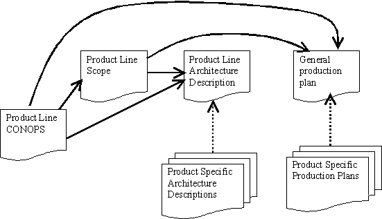
Figure DOCMAP
2.2 References
The following references more fully describe
the methods and theory behind the preparation of this description:
|
[Bachmann 00t]
|
Bachmann F., et. al., The Architecture Based Design Method,
SEI Technical Report, 2000. (http://www.sei.cmu.edu/publications/documents/00.reports/00tr001.html)
|
|
[Bass 98]
|
Bass L., Clements P. and Kazman R., Software Architecture in
Practice, Addison-Wesley, 1998.
|
|
[McGregor 92]
|
McGregor, John D. and Sykes, David A. Object-Oriented Software
Development: Engineering Software for Reuse, International Thomson, 1992.
|
|
[McGregor 01]
|
McGregor, John D. and Sykes, David A. A Practical Guide to Testing
Object-Oriented Software, Addison-Wesley, 2001.
|
|
[Northrop 02]
|
Northrop L., Framework for Software
Product Line Practice, SEI Report, 2002. (http://www.sei.cmu.edu/plp/framework.html)
|
|
Term
|
Definition
|
|
Arcade Game
|
Any game that involves
moving icons interacting with each other and with stationary icons. Points
are scored based on a set of rules.
|
|
Asset
|
A software artifact
that is used in the production of more than one product in a software product
line. Assets often include, but are not limited to, the architecture,
reusable software components, domain models, requirements statements,
documentation and specifications, performance models, schedules, budgets,
test plans, test cases, work plans, and process descriptions. The
architecture is key among the collection of core assets.
|
|
Component
|
A software component
is a unit of composition with contractually specified interfaces and explicit
context dependencies only. A software component can be deployed independently
and is subject to composition by third parties.
|
|
COTS
|
Commercial
Off-The-Shelf: refers to readily-available third-party software products as
opposed to proprietary custom software deliverables
|
|
|
|
|
Economies of Scale
|
The condition
where fewer inputs such as effort and time are needed to produce greater
quantities of a single output
|
|
Economies of Scope
|
The condition
where fewer inputs such as effort and time are needed to produce a greater
variety of outputs. Greater business value is achieved by jointly producing
different outputs. Producing each output independently fails to leverage
commonalities that affect costs. Economies of scope occur when it is less
costly to combine two or more products in one production system than to
produce them separately.
|
|
IPC
|
Inter-Processor
Communication
|
|
Platform
|
A platform is
any complete base of technologies on which other technologies or processes
are built (e.g. operating systems)
|
|
Points of variation
|
Parameters in
the requirements definition that vary exactly how the product operates
|
|
Product Family
|
A set of products
built from a common set of core assets. Technically, a product line need not
be built as a product family, although that is how the greatest efficiencies
are yielded. Likewise, a product family need not constitute a product line if
the resulting products have little to do with each other in terms of market
target or feature relationships
|
|
Product Line
|
A set of
products that share a common set of requirements and significant variability
that satisfy the specific needs of a particular market segment or mission.
Members of a product-line can be treated as a program family, and developed
and managed together to achieve economic, marketing and engineering coherence
and efficiency.
|
|
Regions of Commonality
|
Those portions
of the requirements that we expect each product to meet exactly
|
|
|
|
|
SEI
|
Software
Engineering Institute
|
The
Software Engineering Institute has defined the following definition for a
Product Line:
A product line is a set of products
sharing a common, managed set of features that satisfy the specific needs of a
particular market segment or mission. [Northrop 02]
The
Sykes/McGregor ArcadeGame product line is defined in the scope document.
The
ArcadeGame framework was first described in [McGregor 92] and then refined in
[McGregor 01]. The framework provides a simple architecture and a set of
classes for building arcade games. The present effort will formalize the
architecture and illustrate the concept of a product line.
Regions of Commonality:
|
Area
|
Comments
|
|
Stationary/Moving
Obstacles
|
Every game has elements
that have some degree of substance such as walls, bumpers or sticky spots. Some
elements move over time and come into contact with other elements.
|
|
Scoring
|
Every game has objectives
and award points when those objectives are met.
|
|
ScoreBoard
|
Every game has a
display that shows the player’s status.
|
|
Game playing area
|
Every game has an
area that encompasses the game activity
|
|
Single
player
|
Every game is driven by a single
player.
|
|
Event driven
|
The primary input
for each game is mouse (and eventually, key events)
|
|
|
|
|
|
|
Points of Variation:
There are a number of potential points of variations
that have not yet been identified.
|
Area
|
Comments
|
|
Types
of obstacles and their behavior when they come into contact with movable
objects
|
Many different
types of obstacles may be created and then used by game designers
|
|
Rules
|
Each game will have
its own set of rules. In some cases these rules will be in the form of methods in the
obstacle objects. In some cases it might be in the form of a special rules
object.
It might also be in the form of statements in the main game algorithm.
|
|
Velocity
|
A moving object may move at a
constant rate or it may change speed based on the rules
|
|
Sprite
behavior
|
Sprites can have a
variety of different behaviors. The Sprite may respond to a tick or it
may not.
It may behave the same each time or it may
not.
|
|
How
scores are computed.
|
Each game will
count points differently and may even report the points differently.
|
|
Event
handling
|
Different games
will handle the same event
differently and the same game may handle the same event
differently depending upon the state of the game.
|
|
Speed
|
Some games will
give the user the ability to alter the speed with which the animation
proceeds.
|
|
|
|
|
|
|
The product line will be designed using the Unified Modeling
Language (UML) as the modeling language. The TogetherSoft modeling environment will
be used as the primary design tool. The products will be implemented using the
Visual Studio.Net environment and the C# language.
5.4 Architectural
Qualities
The architecture is created so that
the systems built from that architecture will possess the following qualities:
|
Quality
|
Explicit actions
|
|
Composability
|
Use of parameterization and containment
|
|
Performance
|
Separation of Stationary and Movable Sprites
|
|
|
|
|
|
|
6
Architectural Views
6.1 Main
Architectural Pattern
The
main pattern for the product line is a modified version of the
Model-View-Controller. Shown in Figure MVCTBA, the
pattern separates the responsibility for maintaining the state of the game from
the responsibility for displaying some portion of that information. This basic architecture
can form the basis for all of the games in the Sykes/McGregor ArcadeGame
product line.
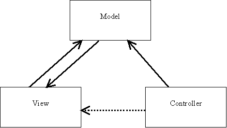
Figure MVC
The modification that
is made to this architecture is possible because each game has a fixed user interface.
Rather than have the Model notify Views when the Model has changed, the Model
can be aware of specific Views and can communicate directly with them. Each game has two
views: a GameBoard where the game action is shown and a scoreboard where the current
score is shown. The revised architecture is shown in Figure MMVC.
Even though it is not
currently a requirement, the MMVC architecture allows for the easy addition of
multiple players on the same game. While it is harder to provide additional game boards for
players in different locations, it is possible to do.

Figure MMVC
6.2 Module
View
This view shows the basic product line
architecture module view.

Figure Game
6.3 Container View
Every
game in the product line has a Game object that is at the top level of the
aggregation hierarchy. The game contains a GameBoard object and a scoreboard object. One
variation is that some games have a speedcontrol object. The GameBoard is the place where game elements reside.
One box inside
another in Figure AGGREGATION indicates that the outer box controls the lifetime
of the inner box and initiates activity in the inner box. This view indicates a
“contains” relationship but only the GameBoard box indicates a “container” in the component
model sense of container. The GameBoard container contains sprite components.
The container maintains two sets of components: those that move and those that
do not. This is an optimization in that it limits the number of sprites that must be
queried for
any given action.
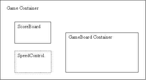
Figure AGGREGATION
7.1 Parameterization
The
games in the product line receive input from their actors through mouse and
keypress events. The GameBoard is parameterized by an event handler
object. All events received by the GameBoard are delegated to this event handler
object.
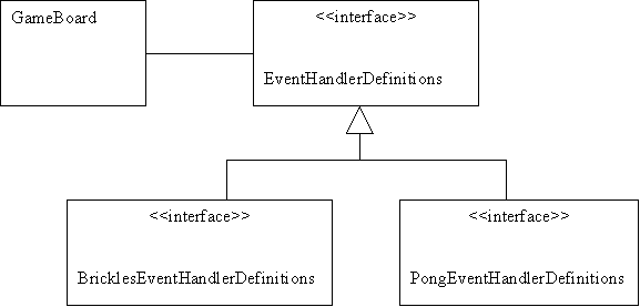
Figure
Parameterized
Each game has its own implementation of the EventHandlerDefinitions
interface. See the general Production Plan to see when the game-specific event
handler class is defined.
Using this approach allows the GameBoard to be reused
unchanged across all of the games in the product line.
7.2 Containment/Parameterization
Hierarchy
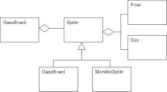
The GameBoard is a container for Sprites. Sprites are
the individual game pieces that are placed on the GameBoard.
StationarySprites are the pieces that do not move. They form the game.
MoveableSprites are the pieces that move during the animation. During Game
construction, the individual Sprites are added to the GameBoard where they will
be held
throughout the life of the game.
Each Sprite is constructed in the game-specific
code. Each Sprite is parameterized by the location and size for that
individual instance. Additional parameters may be required by
some specific Sprite classes.
8
Significant Algorithms
8.1 Move
The central algorithm of the product line is the
animation algorithm. The animation itself is simple. The algorithm is:
Forall
piece in movableSprites
{
piece.move()
}
The
move method in a MovableSprite by default changes
the position of the piece based on velocity of the
piece. This method is overridden to allow MovableSprites to define how they will
move.
8.2 Collision
The major portion of the
algorithm is checking to see if the movement of all the movableSprites has
resulted in any collisions. A collision is the major impetus for actions
of the
system.
The movableSprites are the driving force for the collision algorithm.
Forall piece in movableSprites
{
Forall
piece2 in movableSprites
{
if(piece.overlaps(piece2))
{
throw
Collision
}
}
Forall piece2 in stationarySprites
{
if(piece.overlaps(piece2))
{
throw
Collision
}
}
}
9
Development Approach
In addition to
the increase in technical complexity and rich product feature set, a number of significant
differences are being incorporated in the development approach for the product
line.
In previous projects,
Sykes/McGregor has used a limited number of third-party vendors for software
products that were integrated into products. This system will instead contain
significant portions of COTS software, and there are many effects this will
have on the development process:
·
Inheritance: In some cases, the COTS software will need to be
surrounded in an isolation layer to ensure that we do not become dependent on
the interfaces specified by a single vendor. In other cases, the third-party
software may have certain architectural qualities that are in conflict with our
system’s desired qualities. It may be necessary to compensate for these
qualities if appropriate.
·
Vendor/subcontractor
management: working with another company
in another physical location has known challenges such as support issues,
project management tracking, problem reporting and issue tracking, code release
transfer and acceptance issues, maintenance issues, and security requirements.
Additionally, there may now be coordination among several third-party entities
that needs to be monitored and enabled.
·
Requirements Freeze: Because we are working with external companies, it is
necessary for us to more completely specify working requirements and to freeze
these requirements earlier in the process than on previous projects. Failure to
do so will result in additional development expense for feature change,
integration failures, or additional unplanned work.
·
Testing: The inclusion of COTS software will have fundamental
impacts on the integration and test processes
The use of software components
allows work to be split among different groups, such as between Platform and
Product engineering teams, as well as allotted to outside companies or design
centers. However, there is increased importance in up-front definition to allow
for later integration.
The GameBoard will be
constructed as a reusable asset. It will be implemented as a container. The
container will contain all of the game pieces, referred
to as sprites.
The Sykes design
center will develop the detailed design for the Brickles game. The McGregor
design center will design the architecture and maintain the product
line documentation.
The Architecture Based Design
(ABD) method includes the design, documentation, and verification of the
architecture. This method decomposes
the system into design elements in two steps.
The first step generates subsystem level elements, while a second pass
through the cycle produces component level elements. The steps defined by the architecture design and documentation
process drives this decomposition. At
each step of the decomposition process, the architecture is re-verified to
ensure all of the quality requirements and constraints are still being
met. The process for decomposing the
design elements utilizes the following techniques:
·
Domain Analysis
·
Scenarios – Use Case, Quality Scenarios
·
Consideration of Architecture Styles
·
Defining architecture views (Logical, Concurrency, and
Deployment).
·
Using “Unit Operators” to derive new styles.
·
Mining existing SW to understand what styles exist and
can be used in the target architecture.
·
Software Architecture Analysis Method (SAAM) – Evaluates
the architectural to make sure the quality requirements are being met.
·
Architecture Tradeoff Analysis Method (ATAM) – Assists
with mining Legacy software and evaluating the new architecture.
Several
business constraints also affect our design decisions:
·
the products will be free to the public
·
there are a large number of free game products, we
need to be as good as those or we embarrass the company
Qualities describe how
well the functional requirements are satisfied—where "how well" is
judged by some externally observable/measurable property of the system
behavior, not its internal implementation. The following rank ordering of
architectural qualities will be used when making architectural trade-offs to
achieve the qualities.
|
Qualities seen
during Development
|
Explanation
|
Qualities seen
at Runtime
|
Explanation
|
|
Configurability
|
The ability to change the system’s behavior
|
Performance
|
Responsiveness of the system and how well the system
uses its resources
|
|
Interoperability
|
Ability to make separately developed components work
together
|
Reliability
|
Ability to keep the system running over time
|
|
Scalability
|
Ability of the system to cope with changes to the
supported feature set
|
Verifiability
|
Ease at which the system can be made to demonstrate
its faults through testing
|
|
Flexibility
|
Ability of the system to cope changes to the
existing feature set
|
Security
|
Measure of the system’s ability to resist
unauthorized attempts at usage
|
|
Maintainability
|
Ability to troubleshoot, debug, and correct system
anomalies
|
|
|
|
Portability
|
Ability of the system to run in different computing
environments
|
|
|
|
Reusability
|
Designing a system so that the system’s structure
can be reused in future applications
|
|
|
·
Refer to the use case model for the product line.
·
The user starts the game and begins interacting
with the movableObjects via the controllers. The objects move quickly enough to be interesting to
play.
·
The user starts the game and the objects begin
moving. The colors of the movableObjects and the stationaryObjects against the
background of the board are a pleasing combination to the user.TBD
10.1GameBoardPlayingField
Component
The GameBoardPlayingField
component is the Model in the Modified-Model-View-Controller design pattern.
As such it informs all registered Views when to updateen
a change has occurred.
The GameBoardPlayingField
maintains a list of all model elements. It updates the position of those
elements after a change (usually a clock tick) and notifies each object to redraw
itselfall Views that a change has occurred.
10.1.1 Provides interface
The services provided by the PlayingField
component are listed in the following interface definition:
|
getIcons()startMovement
|
No parameters
|
|
Starts the movement
of MovableSprites in response to Tick
|
|
|
|
stopMovementGetPositions()
|
No parameters
|
|
Stops the
MovableSprites from moving
|
|
|
|
setSpeedRegisterView(View)
|
int – the new speed
|
|
Sets the speed with
which ticks
are produced
|
|
|
|
|
|
|
|
Tick
|
|
|
Pre: isMoving()clock.register()
|
|
Post: a simulation cycle
has completed
|
10.1.2 Requires interface
The services required by the component are
listed in the following interface definition:
|
TTimer
event
|
|
|
|
|
|
|
Input Events
|
|
|
|
|
|
|
|
|
|
|
|
|
|
|
|
|
|
|
|
1.1ClockController
Component
This component drives
the game. It invokes the methods of a callback object periodically to move the game
forward. This is a point at which the software touches the operating system.
This component will isolate the game software from a specific platform.
1.1.1Provides
interface
The services provided
by the ClockController component are listed in the following interface
definition:
1.1.1Requires
interface
The services required
by the component are listed in the following interface definition:
10.2 ArcadeGameView
Component
This component provides one of the Views in
the Model-View-Controller pattern. It is the View that provides the main
playing field.
10.2.1 Provides interface
The services provided by the ArcadeGameView
component are listed in the following interface definition:
|
ModelChanged
|
|
|
Pre: model has changed
|
|
Post: not view.isValid()
|
|
|
|
|
|
|
|
|
|
|
|
|
|
|
|
|
|
|
|
|
|
10.2.2 Requires interface
The services required by the component are
listed in the following interface definition:
1.1InputController
Component
These components
provide input signals of various types into the Model component.
1.1.1Provides
interface
The services provided
by the InputController component are listed in the following interface
definition:
1.1.1Requires
interface
The services required
by the component are listed in the following interface definition:
11 Conclusion
|
Risk
|
Likelihood
|
|
Action
|
|
The architecture
may not be sufficiently general to support all the games in the product line.
|
15%
|
Severe
|
Evaluate the
architecture using ATAM
|
|
The finished
product may be too slow to be an interesting game.
|
25%
|
Severe
|
Continue to prototype
larger and larger portions of the system.
|
The following table lists any remaining Issues to be
resolved with this Product Line document:
|
Issue
|
Status & Date
|
Action
|
|
Whether to use event-driven timer or a fixed loop
|
|
|
|
How to replace a sprite when it is eliminated
|
|
Prototyping
|
|
|
|
|
|
|
|
|
|
|
|
|