What is PCS?
The assignment of a unique PCS telephone number to a customer will facilitate call initiation and completion across regional, national, and international borders. The network will do all the work of tracking a customer, knowing where he or she is, and facilitating a call through the nearest service site.
There are many similarities between cellular telephone service and PCS, but some advantages that PCS has over existing cellular telephone service are; better service quality through the use of digital technology; more compact equipment using advanced antennas technology; increased mobility; and enhanced service features through the use of phone numbers not depending upon geographic location. Also, using digital technology will make the price of PCS cheaper in the near future.
PCS Network Hardware Architecture
A BTS is connected to a BSC. A BSC is a network component that controls one or more BTSs. It performs network management and control functions and decides when and to which BTS the portable will be handed over. An OMC system has many BTSs. It monitors and manages the BTSs and BSCs and is used in controlling and monitoring equipment inside a telecommunications network.
There are more functions in each hardware component, and there are many more network devices and controlling devices which are not mentioned here. This level of detail is sufficient for our simulation purpose. On our PCS simulation system, further assumptions are made for simplification:
- There are OMCs, cells, and portables in the network. A (Radio) cell is a logical concept, but we assume it takes the role of a BTS. We really don't care about a BSC because call hand-over policies are embedded in our simulation policy. Some of its control functions are moved up to the OMC.
- OMCs delineate geographic boundaries, that is, one OMC covers an area as large as one continent.
- An OMC knows all the cells which are aggregated within itself.
- Initially, all portables are registered; i.e., each cell knows about portables within itself.
Major Functions of the System
- The network operator (user) can configure the network at the system boot-up time.
- The simulation system provides the user with the status of the network via either a GUI or in a text window.
- The network operator (user) can reconfigure the network.
- There is a simulation manager which gets simulation events (call initiation, call completion, and portable move, ...) and manages them. The events are feed into the PCS simulation network.
- There is a log file which would contain various information: total calls from each portable, number of call blocks in each cell, and etc.
PCS Network Simulation Architecture

Simulation Component
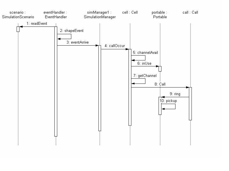
Once the system is operating, the event handler receives an event, wraps it as an event object, and then feeds it to a simulation manager (SM). We assume that there is one SM per OMC. Upon getting an event object, depending upon the start time of the event, the SM may put it into the queue, or dispatch it to the network right away. The events put into the Event Queue are sorted in time sequence. SM also has a dispatcher which constantly looks at the queue, and dispatches the event object whose time is up.PCS Network Component
This module has most of the physical components of the PCS Network described in the previous section. A cell has a predetermined number of channels available, each OMC has a specified number of Cells, and the overall network has one or more OMCs. A call initiation event is sent to a portable, and the portable initiates a call to a receiver specified in the event parameter. The receiver may be in the same cell, in a different cell but in the same OMC, or in a cell in another OMC.The PCS Network has overall knowledge about the entire network. As the dotted region shows, the PCS Network submodule may reside in different host machines from the OMCs, but in the same host as where network operator is located.
Network Control Component
This component keeps information about the network status which can be as small as a simple file, or as large as a corporate database. In our simulation, it will be kept as a small file which would contain the call block rate of each cell. But we can extend it to have more complex structure of data and to have a database query model to manage them. This component also provides an interface to an operator. The interface can be as simple as a console window, or as complex as a GUI environment.Use Case Requirements
1.1 Configuring the network
User:Network Operator
Use scenario: The operator sets up the initial configuration file and boots-up
	the system. The configuration can be done interactively, or in batch
	mode in which case there would be several configurations available
	to the operator.

Frequency: done only one time at the system initialization
Criticality: How the network is configured is not a critical issue, but it is
	useful to have more than one way of configuring the network.

2.1 Report network status
User: network monitor
Use scenario: Upon the request from the network operator, network monitor
	reports the network status to the operator
Frequency: happens on demand
Criticality: This is a necessary feature.

2.2 Gather network status information
User: network monitor
Use scenario: The network monitor gathers status information of the network
	periodically. The period is set default at the system boot-up time,
	but the network operator can change it if necessary.
Frequency: happens periodically
Criticality: This is a necessary feature.

3.1 Reconfigure the cell
User: network operator
Use scenario: The network operator sees that cell No.4 has call drop rate
	higher than threshold value. He/she decides to increase the number of
	channels that the cell can handle.
Criticality: This is a necessary feature.

4.1 Read event and launch it to the network

4.1.1 Get an event and shape it as an event object
User: Event Handler
Use scenario: The event handler reads events from a file. (Or, from a random
	number generator which generates events.) Then, it creates an event
	object according to the event, and send it to the corresponding SM.
4.1.2 Put the event object into the Event Queue
User: simulation manager
Use scenario: Once getting an event object from the event handler, if the event
	fire time is not up yet, the SM puts it on to the event queue according
	to time sequence of the event.
Criticality: This is not necessary for simple simulation, but necessary for
	advanced simulation.

4.2 Dispatch event object
User: simulation manager
Use scenario: Simulation manager gets an event from the front side of the
	queue, and dispatches the event object to the corresponding network
	component (either to the cell or portable?).
	If the event fire time was up when the event object was received from
	the Event Handler, the SM dipatches the event object right away.
Criticality: This is a necessary feature.

4.2.1 Call arrival
User: Cell
Use scenario: Upon getting the event from the SM, the cell asks the portable
	if it is in use or not. If it is, the call event is dropped.
	If it is not, the cell provides a channel for the portable, and
	creates a call object.

4.2.2 Call termination
User: portable
Use scenario: Upon getting the event from the SM, the portable terminates
	the call. The call object is deleted, and the channel is released.
Criticality: This is a necessary feature.

4.2.3 Portable move
User: Cell
Use scenario: Upon getting the event from the SM, the cell first checks
	if the portable was in use. If yes, and if the destination cell is
	free of channel, turns the portable over to the destination cell.
	Then, the original cell releases the channel assigned to the portable,
	and the new cell allocates a new channel for the portable.
	If the portable was not in use, the old cell simply drops the portable
	from its list, and the new cell adds it to its list.
Criticality: This is a necessary feature.


5.1 Log the call block
User: cell
Use scenario: A cell needs to allocate a channel for for a new call or handoff
	call, but there is no channel available. Then the cell writes the call
	block information to a log file.
Criticality: This is a necessary feature.
Analysis Model
Object Model

Object Interaction Model