This website is preserved for historical and scholarly reference and is no longer actively maintained.
2.4 Adding Functionality to a Watch Model
As the final exercise in our Watch example we will build new
functionality into an existing sub-application by modifying its state machine
definitions. In the Graph Browser, open the ‘Stopwatch’
WatchApplication diagram. The diagram will appear as shown in
Figure 2-8.
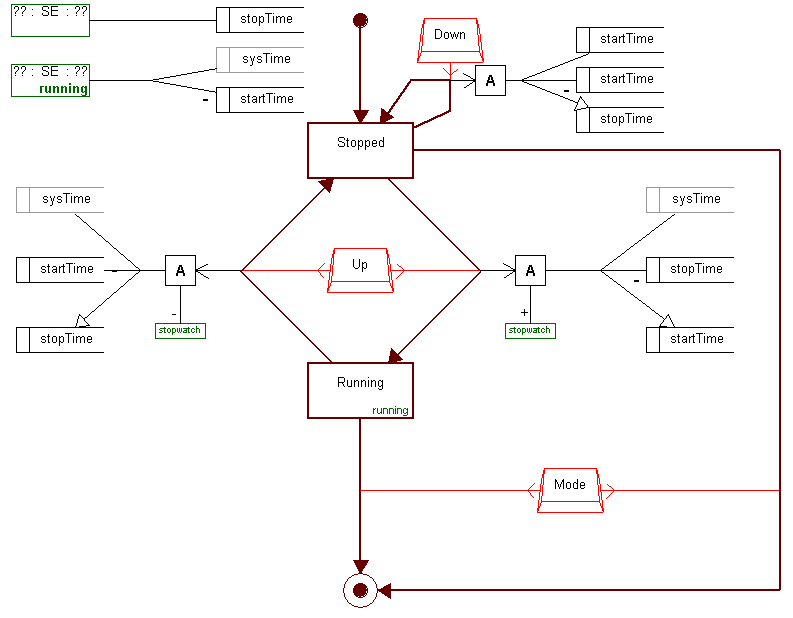
Figure 2-8. The ‘Stopwatch’ WatchApplication diagram.
As
the name says, ‘Stopwatch’ is a sub-application that enables the
user to time the length of various events. When this application is activated,
it immediately enters the ‘Stopped’ state showing the zeroed time
counter on the display. From here there are three ways to proceed. Pressing
‘Mode’ will deactivate the application and pass the control back to
the top-level state machine. Pressing ‘Down’ will reset the counter.
Pressing ‘Up’ will start the counter by setting the start time and
entering the ‘Running’ state. Pressing ‘Up’ again while
in ‘Running’ state will stop the counter by calculating the stop
time and returning back to the ‘Stopped’ state. It is also possible
to terminate the application by pressing ‘Mode’ while in
‘Running’ state.
However, there is still something missing from our
‘Stopwatch’ sub-application: it does not have a lap-time function.
Basically, to add such a functionality we need describe that when
‘Down’ is pressed while the ‘Running’ state is active,
the lap-time is calculated (as it is not available as a pre-defined entity) and
a new ‘LapTime’ state will be activated, showing the lap-time on
display. When ‘Down’ is pressed again, the control is dispatched
back to the ‘Running’ state.
Before proceeding with any new functionality, let us
explore the basic mechanism of how displayed time units are controlled. Each
application state refers to a display function that specifies how to calculate
the time shown while the state is active. Display functions are presented with
DisplayFn objects (two green boxes at the top of
Figure 2-8) and each of them can be
shared by many states. The green text at the bottom right corner of the state
symbol indicates which display function it refers to. There are two display
functions in our Stopwatch application, one called ‘Running’ and one
without a name. Leaving the name blank is the way to define a default display
function – all the states without an explicitly named display function
will use this nameless display function by default. The display function
definition also sets the key time unit that will be shown as the middle one on
the display. The actual time unit arithmetic is based on variables and variable
references that are services built into our Java platform. For example, the
display function ‘Running’ returns the current counter time by
subtracting the value of ‘startTime’ variable from the value of the
‘sysTime’ variable reference that carries the current system
time.
As for the first task of creating the lap-time
functionality, create a new State object and enter ‘LapTime’ as its
name. As the default display function suits for our purposes here and as we do
need a blinking display, you can leave other property fields blank. Proceed then
by defining a Transition relationship from the ‘Running’ state to
‘LapTime’ and then another from ‘LapTime’ back to
‘Running’.
The next thing we need to do is to associate the
‘Down’ button as a triggering event for both of these transitions.
We do not need to define a new button as we can reuse an existing button
definition. Select the existing ‘Down’ button, copy it with Ctrl+C,
and paste it with Ctrl+V. The pasted button will follow the cursor: move it down
to near the ‘LapTime’ state
(
Figure 2-9) and click to place it there.
Associate this button with both transitions between ‘LapTime’ and
‘Running’ states by choosing each relationship, selecting
Add a
New Role... from their popup menus and connecting the new roles to the
‘Down’ Button. The diagram should now look similar to
Figure 2-9.
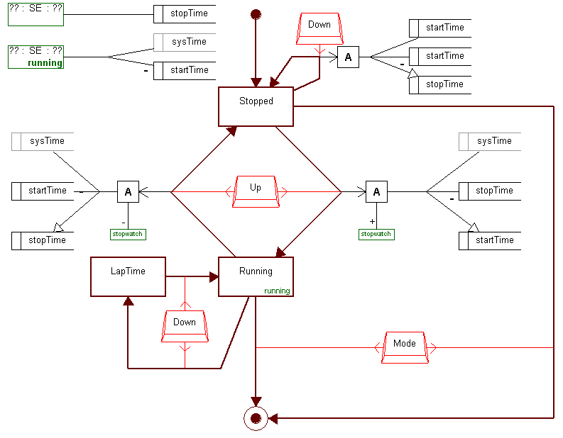
Figure 2-9. The ‘Stopwatch’ diagram with definitions for a new state.
To
complete the implementation of the new functionality, we need to define the
actions that are required for calculating the lap-time during the transition
from the ‘Running’ state to the ‘LapTime’ state. First
create a new Action object, and add a new role to it from the Transition
relationship going from ‘Running’ to ‘LapTime’. Then
reuse the sysTime VariableRef object and startTime and stopTime Variable objects
from this same graph as shown in
Figure 2-10.
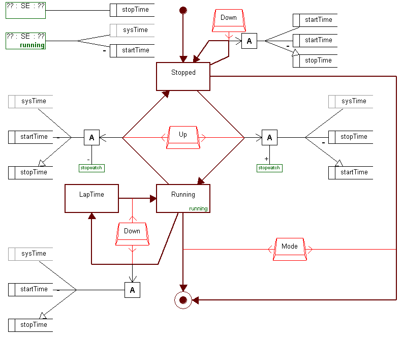
Figure 2-10. The extended version of ‘Stopwatch’ sub-application.
To
define the calculation relationship between Action, VariableRef and Variable
objects, hold shift down and select first the Action object, then
‘sysTime’, then ‘startTime’ and finally
‘stopTime’ and then select Connect from the popup menu. From
the list of possible relationship combinations, choose ‘Set (ActionBody
Action) (Get sysTime) (Minus startTime) (Set stopTime)’ and accept the
following dialog as it is. The definition of lap-time functionality has been now
completed. The lap-time will be shown correctly as our calculation stores the
lap-time value in the ‘stopTime’ variable that is attached to the
default display function used by the ‘LapTime’ state. You can now
try it out by generating the code and running the test environment.


